3 Way Switch Wiring : 3 Way Switch Wiring Diagram : Red wire (traveler or switch wire).. With these diagrams below it will take the guess work out of wiring. (learn more about how our awesome backlit switches work here) even that one is still pretty straight forward though, here are some diagrams that show the single jumper required on the back of the switch. Two of these take traveler wires that go from one switch to the other. The circuit consists of a two way switch at each end (top and bottom switches in fig 2) and an intermediate switch in the middle. You will terminate from the last comment do you like fixture.
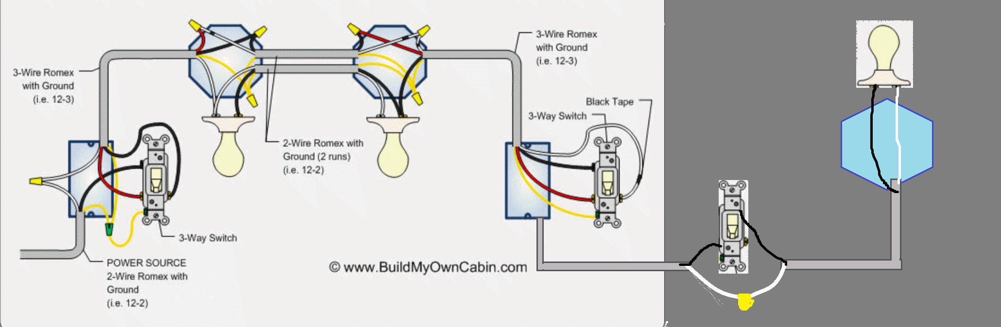
Wiring a 3 way switch to multiple light fixtures is pretty much the same as wiring it with one light fixture. (learn more about how our awesome backlit switches work here) even that one is still pretty straight forward though, here are some diagrams that show the single jumper required on the back of the switch. In this configuration, the power enters the first switch, and the light fixture is placed after the second switch. Then running you're 3 wire with your travellers. Three way switching schematic wiring diagram.
3 Way Rotary Lamp Switch Wiring Diagram For Your Needs from www.familyhandyman.com 3 way switch wiring diagram. The black and red wires between sw1 and sw2 are connected to the traveler terminals. In this diagram, the electrical source is at the first switch and the light is located at the end of the circuit. Connect the two remaining traveler wires to the two brass or light colored screws. Pick the diagram that is most like the scenario you are in and see if you can wire your switch! It shows the components of the circuit as simplified shapes, and the skill and signal friends along with the devices. This terminal is usually identified by a darker colored screw. These wires connect to the brass screws on the switch.
In this case, electricity flows through the ceiling box from the first switch to the second switch.
With these diagrams below it will take the guess work out of wiring. For the third terminal, one switch is connected to the hot supply wire while the other switch is joined to the light. The only items not visible in the image are the switch blades, shown as purple in the. Notice that the wire connected to the com terminals is looped straight through. After running power to your first 3 way. In this case, electricity flows through the ceiling box from the first switch to the second switch. Of the three bilge pump switches the only one that's not extremely simple is the backlit auto/manual bilge pump switch. Connect the ground wire to the green screw. The switches are shown in a horizontal position to make it easier to visualize. (learn more about how our awesome backlit switches work here) even that one is still pretty straight forward though, here are some diagrams that show the single jumper required on the back of the switch. A wiring diagram usually gives opinion approximately the relative outlook and pact of. It shows the components of the circuit as simplified shapes, and the skill and signal friends along with the devices. C) the wires from the power source go from switch to switch, and then go to the light.
3 way switch wiring diagram. (learn more about how our awesome backlit switches work here) even that one is still pretty straight forward though, here are some diagrams that show the single jumper required on the back of the switch. The circuit consists of a two way switch at each end (top and bottom switches in fig 2) and an intermediate switch in the middle. This terminal is usually identified by a darker colored screw. With these diagrams below it will take the guess work out of wiring.
3 Way Switch Wiring Diagram Power At Switch | Wiring Diagram from annawiringdiagram.com It shows the components of the circuit as simplified shapes, and the skill and signal friends along with the devices. C) the wires from the power source go from switch to switch, and then go to the light. With these diagrams below it will take the guess work out of wiring. Insulated wire nuts to connect / join wire together, variety of sizes out there so make sure you obtain the correct size. With conventional wiring, the common wire from one switch connects to line, the common wire from the other switch connects to the load (lights). Wiring diagram 3 way switch with light at the end. It is the best and easiest method of wiring 3 way switches. The circuit consists of a two way switch at each end (top and bottom switches in fig 2) and an intermediate switch in the middle.
This terminal is usually identified by a darker colored screw.
In this case, electricity flows through the ceiling box from the first switch to the second switch. These wires connect to the brass screws on the switch. The switches are shown in a horizontal position to make it easier to visualize. A wiring diagram usually gives opinion approximately the relative outlook and pact of. C) the wires from the power source go from switch to switch, and then go to the light. This is a basic 3 way switch wiring method. In houses, switches should always be mounted vertically (up and down). Red wire (traveler or switch wire). Connect the two remaining traveler wires to the two brass or light colored screws. Pick the diagram that is most like the scenario you are in and see if you can wire your switch! Three way switching schematic wiring diagram. Connect the wire marked common to the black or dark colored screw. After running power to your first 3 way.
The wiring method will depend on whether your power goes to the switch first or the light first. In this diagram, the electrical source is at the first switch and the light is located at the end of the circuit. In this configuration, the power enters the first switch, and the light fixture is placed after the second switch. After running power to your first 3 way. Pick the diagram that is most like the scenario you are in and see if you can wire your switch!
Leviton Decora 3 Way Switch Wiring Diagram 5603 ... from i.ytimg.com Three way switching schematic wiring diagram. Wiring a 3 way switch to multiple light fixtures is pretty much the same as wiring it with one light fixture. This terminal is usually identified by a darker colored screw. The ground wire is pigtailed with a wire connector at the switch boxes and the ceiling box. These wires connect to the brass screws on the switch. In this configuration, the power enters the first switch, and the light fixture is placed after the second switch. This is a basic 3 way switch wiring method. With these diagrams below it will take the guess work out of wiring.
How to wire a three way light switch.
Connect the ground wire to the green screw. Two of these take traveler wires that go from one switch to the other. Of the three bilge pump switches the only one that's not extremely simple is the backlit auto/manual bilge pump switch. The only items not visible in the image are the switch blades, shown as purple in the. Wiring diagram 3 way switch with light at the end. For the third terminal, one switch is connected to the hot supply wire while the other switch is joined to the light. Three way switching schematic wiring diagram. Insulated wire nuts to connect / join wire together, variety of sizes out there so make sure you obtain the correct size. A wiring diagram usually gives opinion approximately the relative outlook and pact of. How to wire a three way light switch. The switches are shown in a horizontal position to make it easier to visualize. This is a basic 3 way switch wiring method. This might seem intimidating, but it does not have to be.